Arduino based DCC command station
This project is about building a cheap DCC command station. What is DCC, I hear you ask. DCC stands for Digital Command Control and is a system that is widely used in digital model railroads. There is a fairly good description of DCC on the NMRA site.
Such an elementary base station able to produce DCC consists of three main components:
- An Arduino UNO
- An Arduino motor shield
- The DCC++ software
Ingredients
For the Arduino UNO I chose the (fully compatible) Velleman ATmega328 UNO ontwikkelboard.
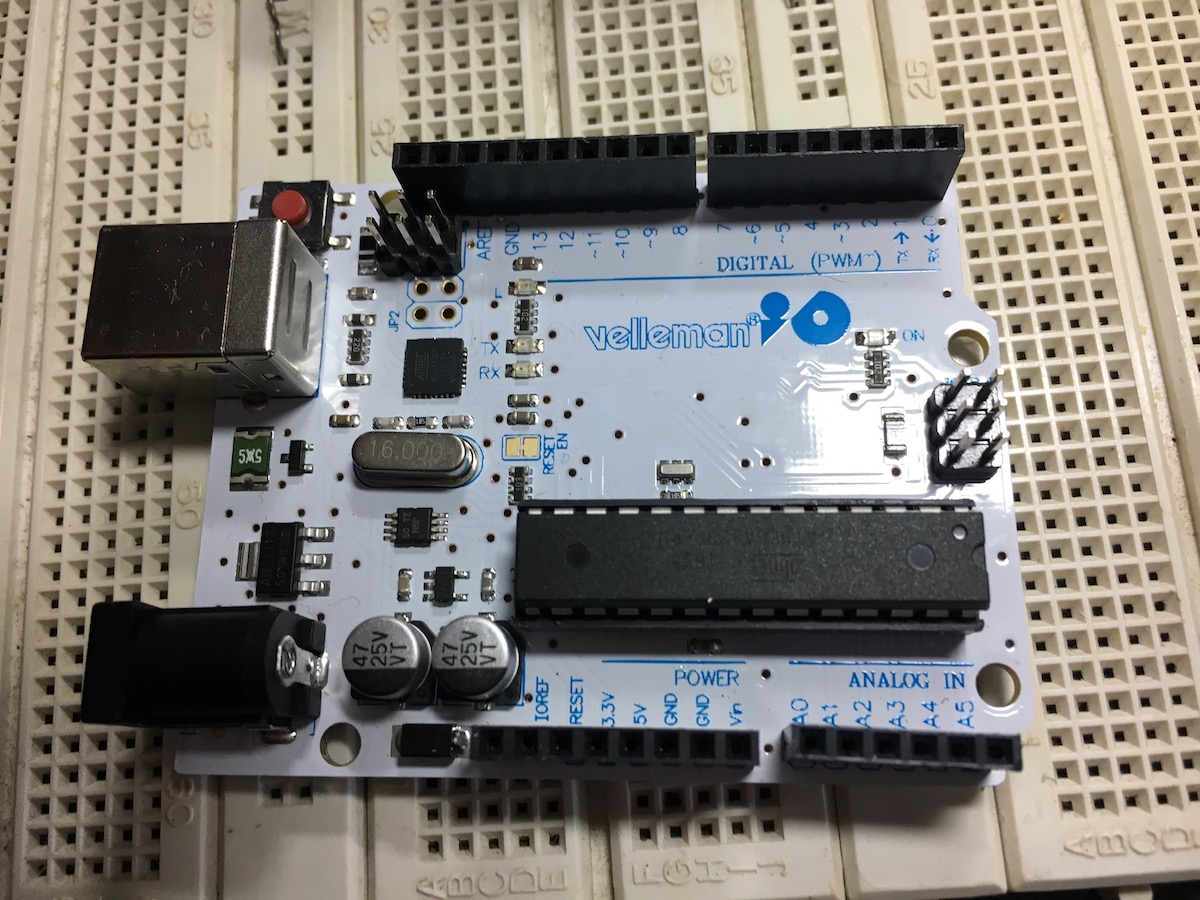
ATmega328 UNO
For the motor shield I chose the Velleman VMA03 motor shield.
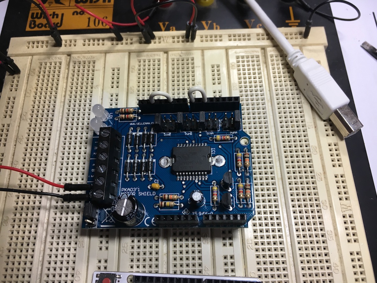
Velleman Motor Shield for Arduino
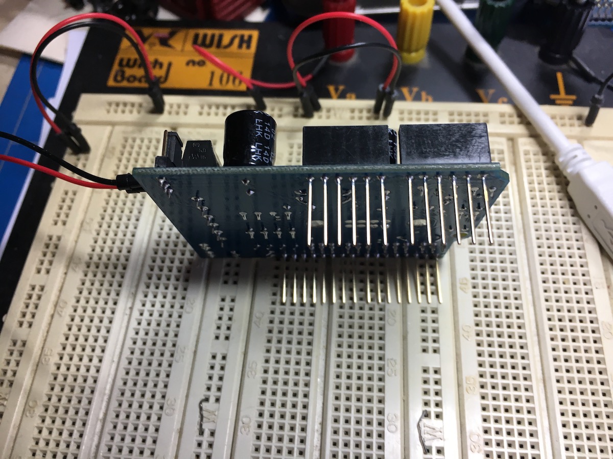
Velleman Motor Shield for Arduino on it’s side
The motor shield can be stacked on top of the UNO:
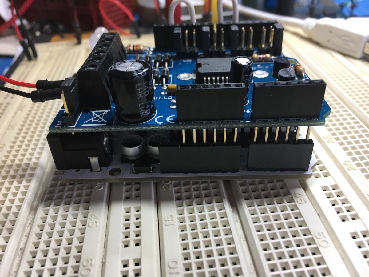
UNO plus motor shield stacked
Software
The DCC++ software can be downloaded as freeware from Github.
Compatibility
Although the Velleman kits are indeed functionally and electrically compatible, some changes must be made to the code and to the hardware to make things work.
Cook book
The cook book I used is a series of four video’s that explain in a very good way to build the hardware we need for this project.
Changes
The video’s assume the use of the original Arduino boards, so there are some differences that I will describe below.
Hardware changes
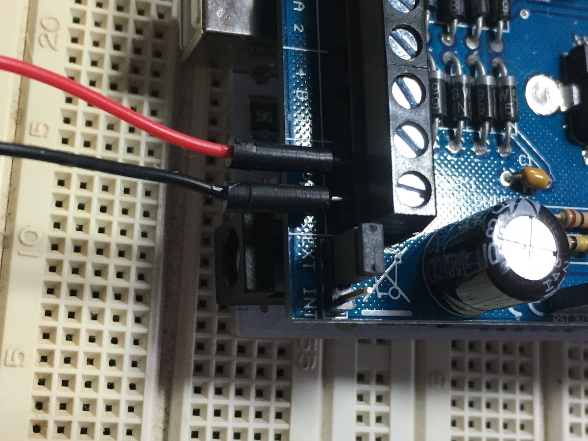
To work with the Velleman kit we must wire some jumpers differently from what’s in the videos. See description below the picture.

Jumpers for PWR etc
The motor shield has two outputs, A and B. Output A will drive the DCC signal for our programming track and output B will drive DCC for the main track.
The programming track, output A:
- PWRA switches the power of the programming track and is set to connect to pin 3.
- DIRA determines the direction of current for the DCC signal and is set to pin 7.
The main track, output B:
- PWRB switches the power of the main track and is set to connect to pin 11.
- DIRB determines the direction of current for the DCC signal and is set to pin 13.
Timing of DCC signal:
Now we need to connect two more pins. Two internal clocks are used to determine the timing of the direction of DCC current. The resulting output is on pin 5 for the programming track and has to be connected to pin 7 (the white wire used as jumper on the top right in the picture), and on pin 10 for the main track and has to be connected to pin 13 (the white wire used as jumper on the top left in the picture).
Now we must take care of our motor shield so that it gets it’s power from an external source, not from the Arduino.
Int/Ext power jumper
Right next to the external power terminal there’s a jumper that can be set to Int, in which case the motor shield will draw its power from the Arduino on which it is stacked.
We definitely do not want that because that Voltage would be way too low for our purpose. We want to use external power for the motor shield.
So we set this little jumper to ‘Ext’.
This concludes the changes in the hardware.
Software changes
There are two files that must be changed:
DCCpp_Uno.h
This file contains a line setting the variable DIRECTION_MOTOR_CHANNEL_PIN_A to 12. The Vellman kit can not use this pin, so we change this to 7:
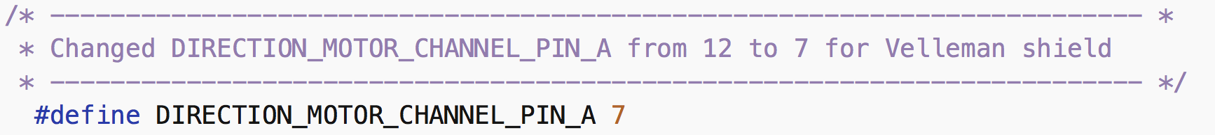
Code change 1
Then there’s the file:
DCCpp_Uno.ino
This file contains code to set a pin for monitoring at program startup. The Velleman can not use the coded A5 pin, so we change this code to set it to A4:
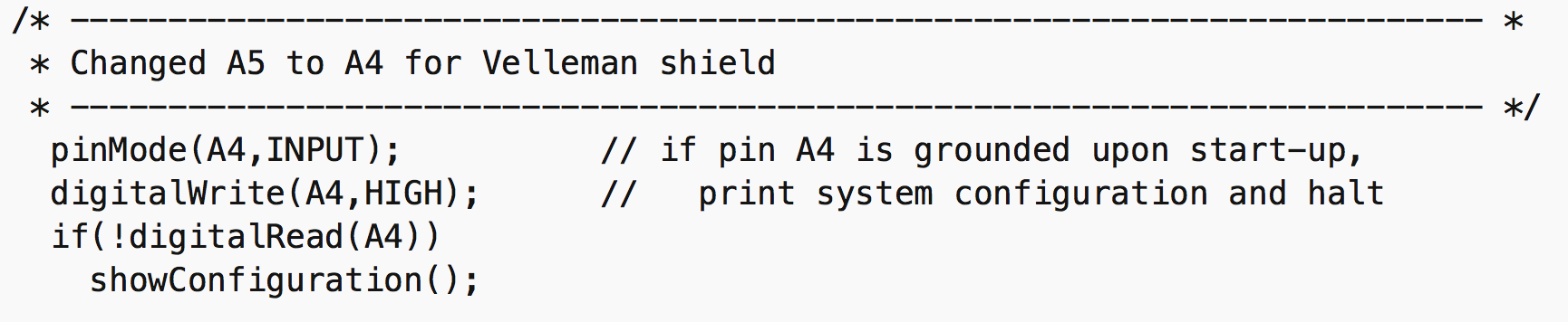
Code change 2
And that’s it! Now we load the code and hook up our DCC command station!