In the May newsletter of our local branch of the VERON, I came across a second hand manual antenna tuner (MFJ-971). It can alter the inductive and capacitive impedance of antenna’s so they match impedance of the transmitter. By doing so it maximizes the amount of power output of the transmitter that goes into the antenna and minimizes the reflected power that comes back from the antenna. Also see this page.
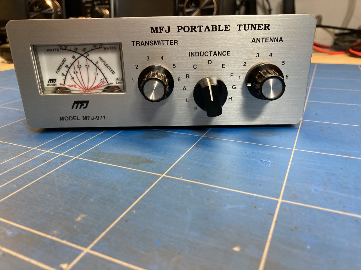
In picture 1. you can see the front panel, a dual needle meter, a transmitter side and antenna side variable capacitor, and a variable inductor in the middle.
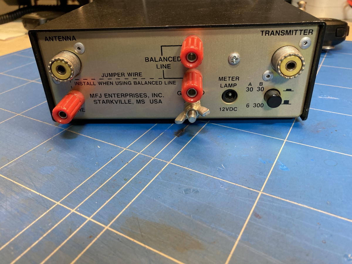
In picture 2. you can see the back side of the device with a connection for the transmitter and several connections for an antenna, SO-239, balanced line and long-wire. Also, there is a ground connection, a 12V DC plug for lighting the frontpanel, and a switch for different power ranges.
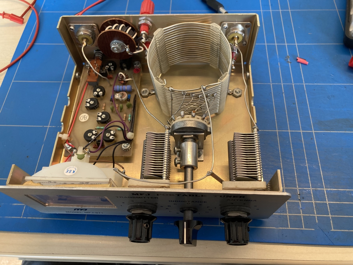
Curious hobbyist that I am, of course I want to see what’s in the box, so I opened it up. (picture 3.)
Looking carefully you can see that it is a T-matching circuit. The signal from the transmitter comes in from top left (with the silver colored wire to the circuit board). It is lead through a little coil and then goes on to the transmitter side variable capacitor. From there it is connected to one side of the BIG switchable coil that looks a bit like a beer can. after that it goed through the antenna side variable capacitor and then out again to the antenna terminal (top right).
The little coil the lead passes through is used to tap the signal to be able to measure the forward an reverse power to and from the antenna. The rest of the circuit on the board drives the two meters in the front panel to make those currents visible.
Haven’t tested it yet, but looking forward to doing so!