As you could have read in my previous post, I decided to create my own digital clock to replace the old nixie clock (R.I.P).
Components
The components I will be using are:
- The casing of the old nixie clock
- An Arduino Uno (for programming the ATMEGA328p chip. Actually that chip is the heart of the Arduino, only the Arduino boards have added stuff to make it more accessible, and to connect it through USB with a computer.
- A RTC (Real Time Clock) module, the DS3231. It keeps the time and date, takes care of leap-years – at least from now up until 2099…
- A 7 segment display module, the TM1637). It has four digits and a semicolon in just the right place.
- Some buttons and a switch
- A perforated printed circuit board
- Some wiring
Software
And of course there was some programming involved. Should you be interested, here is a link to my GitHub repository. Dive into the folder named ‘gawclock’ and open up the file ‘gawclock.ino’. That’s the program running the clock.
Starting the build
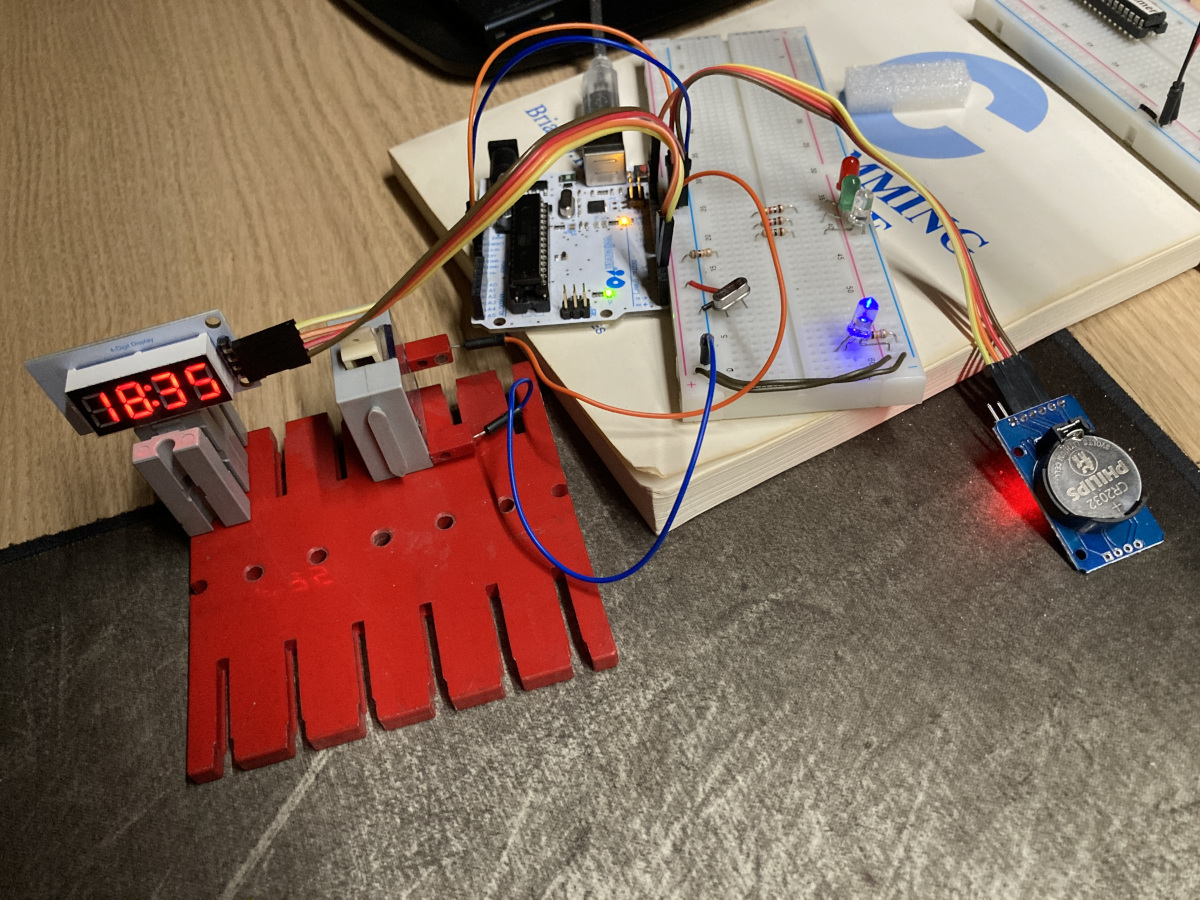
First I hooked everything to an Arduino board to be able to program the ATMEGA38p chip.
In the center in the back is the Arduino Uno.
In the picture you can see it’s first iteration, it shows the time on the display on the left.
The little module on the right is the clock module. It has a CR2032 battery to keep the time when main power goes of.
Closer look
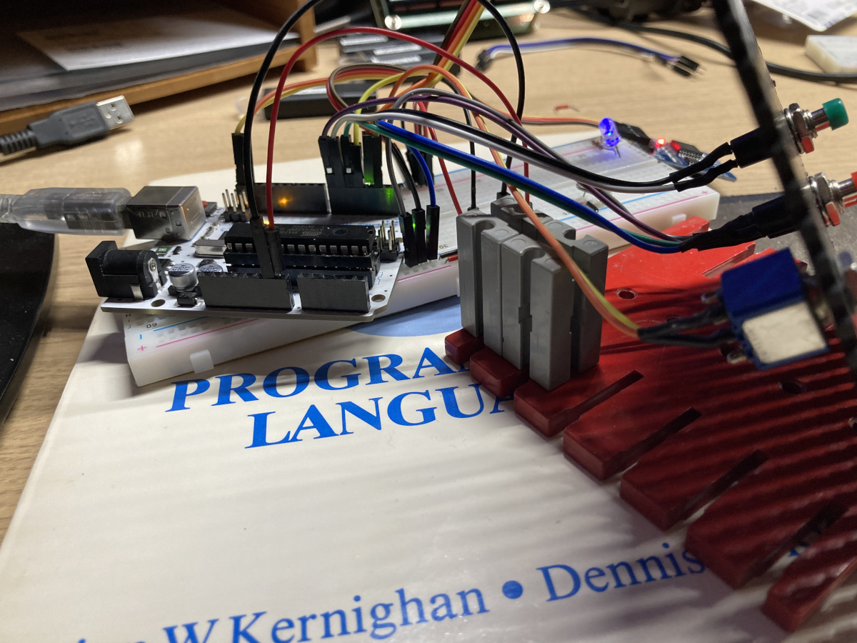
Here’s a close look after I hooked up the switch and buttons.
It seems like quite a mess (and frankly, it is). But no worries things are getting better…
The buttons
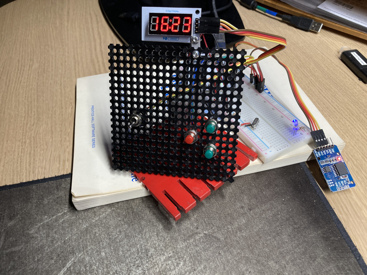
The left switch in the picture can be toggled to show either the time or the date.
The red button starts the ‘settings’ process. With each press, it goes through 7 settings:
1. Year, 2. Month, 3. Date, 4. Hour, 5. Minute, 6. Second, 7. Brightness.
The upper green button moves the value of a setting up, the lower green button moves in down.
Finalizing
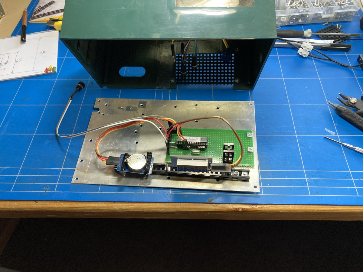
First I used an experimental PCB (Printed Circuit board) on which I soldered the components and connectors.
I used rather long (two-part) wires to hook up the switch and buttons on the back of the casing to the connectors on the PCB.
I could mount everything thanks to holes in the bottom board of the original casing.
The backside

Here’s a look at the back,with the buttons and a connector for a 5Volt barrel jack.
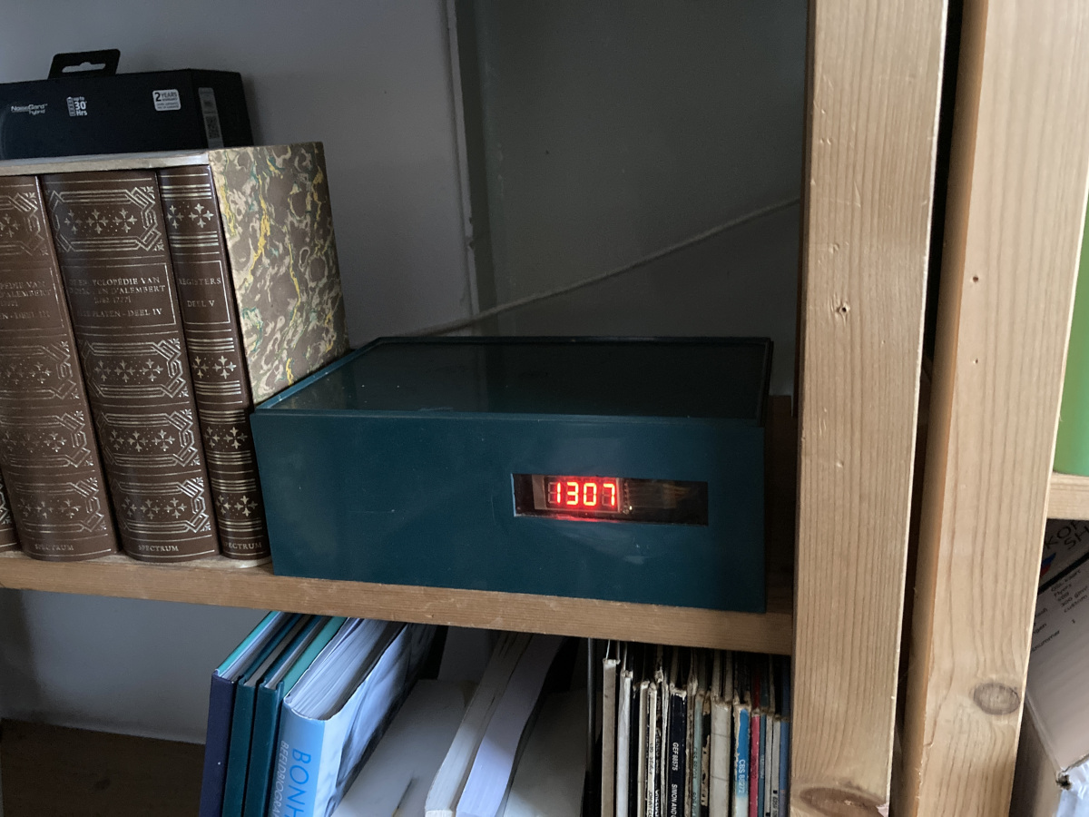
The result!
Tadaaa…. Here it is: the new clock:
Een ode aan Pa
Precies wat ik ook dacht Joost! (en de reden voor het hergebruik van deze behuizing)