Totem Rotary encoder – explained
How does it work?
I was fumbling around with the Totem Mini Lab’s Side Panel 1, especially with the rotary encoder that s mounted on this side board. At first, I could not make heads or tails from it, but, using my oscilloscope, I’ve figured it out now.
Contacts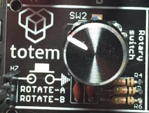
It appears that both connections – labelled ‘Contact A’ and ‘Contact B’ give pulses. In the pictures below, Yellow indicates Contact A, and Blue indicates Contact B. The contacts are normally open and, when closed, they pull the outputs to ground.
Pulses
When turning the know clockwise, the pulse from contact B comes just before the pulse from contact A and just the other way around when turning counter-clockwise (have a look at this blog post). Now we can do some coding to decode this behaviour.
Algorithm
So, what does this code have to do? It has to detect the direction of motion, right (clockwise) or left (counter-clockwise). We are going to have a closer look at what happens exactly.
What happens?
Let’s call the contacts A and B. When we don’t do anything, both pins will be high, so the value on the pins will be binary ‘11’, or decimal 3. We are going to use two pins on our Arduino to connect to these contacts, I used:
- pin 16 (A2) for Contact A
- pin 17 (A3) for Contact B
Values
How do we create a decimal value from two individual pins? We do that in a calculation:
Decimal value = 2 x (pin 16 value) + pin 17 value
This involves a multiplication and an addition. We can change the calculation to make it faster:
Decimal value = (pin 16 value)<<1 | pin 17 value
In this calculation ‘<<1’ means: shift the value 1 bit to the left (which is equivalent to a multiplication by 2), and the ‘|’ stands for the logical OR operation (in this case, because we just shifted a value 1 bit to the left, the rightmost bit has become a zero and OR’ing the value of one other bit will in effect add it to the other value).
Possibilities
In the t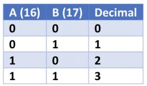 able on the right we can see all possible binary combinations and their values.
When turning the button these values change. The pins are normally high, so the value is decimal 3 (11) when we don’t do anything.
Clockwise
When we turn clockwise, contact B is made first, resulting in a value of 2, and then contact A is made, giving us the value 0, then contact B is released, giving us value 1 and at last contact B is released, then we’re back at value 3. So, the sequence of changing values is 3, 2, 0, 1, 3.
Counter-clockwise
When turning counter-clockwise the sequence of events is reverse, so the values will be reverse as well: 3, 1, 0, 2, 3.
Explanation
We can see this in these pictures (remember, B is blue, A is yellow):
-

- Values with clockwise

-

- Values with counter-clockwise

Transitions
The sequences we mentioned each signify one click of the knob. When we take a closer look, the first two values of each sequence are unique per direction. So we only have to look at the transitions from 3 to 2 (indicating a clockwise turn) and from 3 to 1 (indicating counter clockwise turn).
Detection
To be able to detect a transition, we would have to store the value of the two pins between two loops. Then, next time, we can compare them. We are only interested in situations where:
- the previous value is 3
- the current value is different from the previous value
- the current value is 1 or 2
If all that is true and the current value is 2, this indicates a clockwise turn, whereas when the current value is a 1 this indicates a counter-clockwise turn.
Okay, what can we do with it?
Example program
Now we know how the Rotary Encoder works and how we can detect which way it turns, we can put it to work. To show this in code, I took a program that displays a binary counter using eight bits, eight LED’s attached to the Arduino. The speed was set to change at a regular interval using a ‘wait-time’. Now let’s use the Rotary Encoder to be able to change the speed.
Actions
When turning clockwise, we want the speed (or frequency of the counting) to go up, so the wait-time has to go down. And of course, when turning counter-clockwise, we want the speed (or frequency of the counting) to go down, so the wait-time has to go up. I chose an increment / decrement value of 10, because otherwise the change in speed was barely noticeable and we had to turn very long (many clicks) to achieve a significant change in speed.
You can find the code of the sketch at my GitHub page.