Below you can see my audio stack. At this moment it is in use for work related Teams and Skype meetings, later on, when I passed my exam and have obtained my license, I will also use it for HAM voice activities (QSO’s).
The stack:
Components
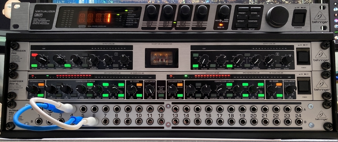
One by one I will describe the components from top to bottom as shown in the picture.
Virtualizer
The virtualizer is a two channel effects processor. It has a very elaborate range of effects on board. Amongst others there are 12 reverb effects and several delays and echo’s. Further effects options include modulation, amp simulation, distortion and special effects, as well as effective dynamic and psycho acoustics processing.
Preamplifier
This two channel microphone / line preamplifier can be used to get microphone signals up to line level as well as act as a preamp for bass and regular guitars. The two channels can be coupled so that the controls of the left channel control them both. It supports condenser microphones with the 48 Volt phantom power these mic’s need. Dynamic microphones with their own characteristics will be amplified just as well. There is a lo-cut (or high-pass) filter that works perfectly to filter out rumbling sounds and the low parts of the voice. It also contains a two band equalizer per channel (which I don’t use). And of course the output level can be justified.
Compressor
To simply call this machine a compressor doesn’t do it justice. It’s a dual-channel Expander/Gate/Compressor/Peak Limiter. It can compress mono/stereo signals and provide noise suppression, without loss of high frequencies. It can increase vocal presence and energy; It provides limiting, or smoothing out extremely-high signal peaks. Additionally, it features an integrated Dynamic Enhancer, a De-Esser, a Low-Contour filter and a switchable Tube simulation for extra warmth and transparency.
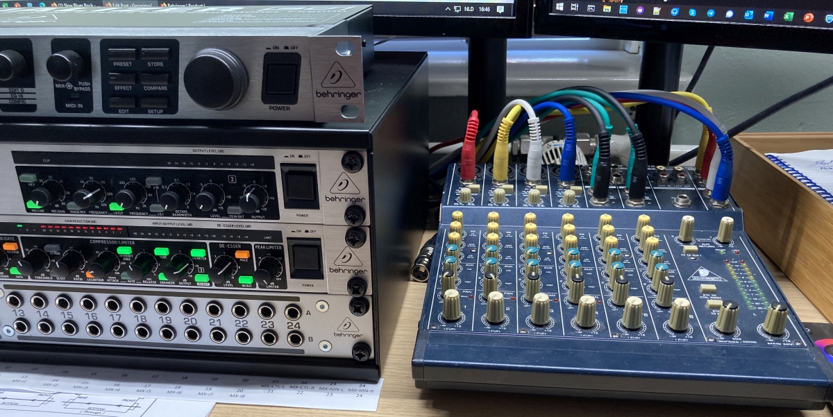
Patchbay
A patchbay is a simple yet clever device. Mine contains 48 balanced TSR jack connections, both on the front as well as on the back. These connectors are split into two rows, row A and row B. Each of the 24 pairs can be switched in Normal, Half-normal or Thru modes. Mine are all set to Half-normal mode, which means that the normal, default connections on the back are connected from the top row (A) to the bottom row (B). On the front you see nothing of these connections. On the picture below you can see two small cables connecting A3 to B5 and A4 to B6. This bypasses the Virtualizer for now, by tapping into it’s outputs on A3 and A4 and feeding them into the input of the next device in the chain. In the back there’s a lot of cables, in the front we have a tidy look and can patch things easily.
Mixer to patch in:
Connections A21-A24 of the patchbay are connected to the outputs of my little mixer. B13-B20 are connected to channels 1 through 8 of that mixer, so I can patch those into the stack as well.