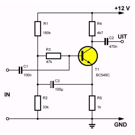
Today I thought I’d play around and build a simple amplifier, just for fun. I started out searching for circuit diagrams for “one transistor amplifier BC337“, just because I have a couple of those BC337’s laying around. I found a schematic that you can see to the right:
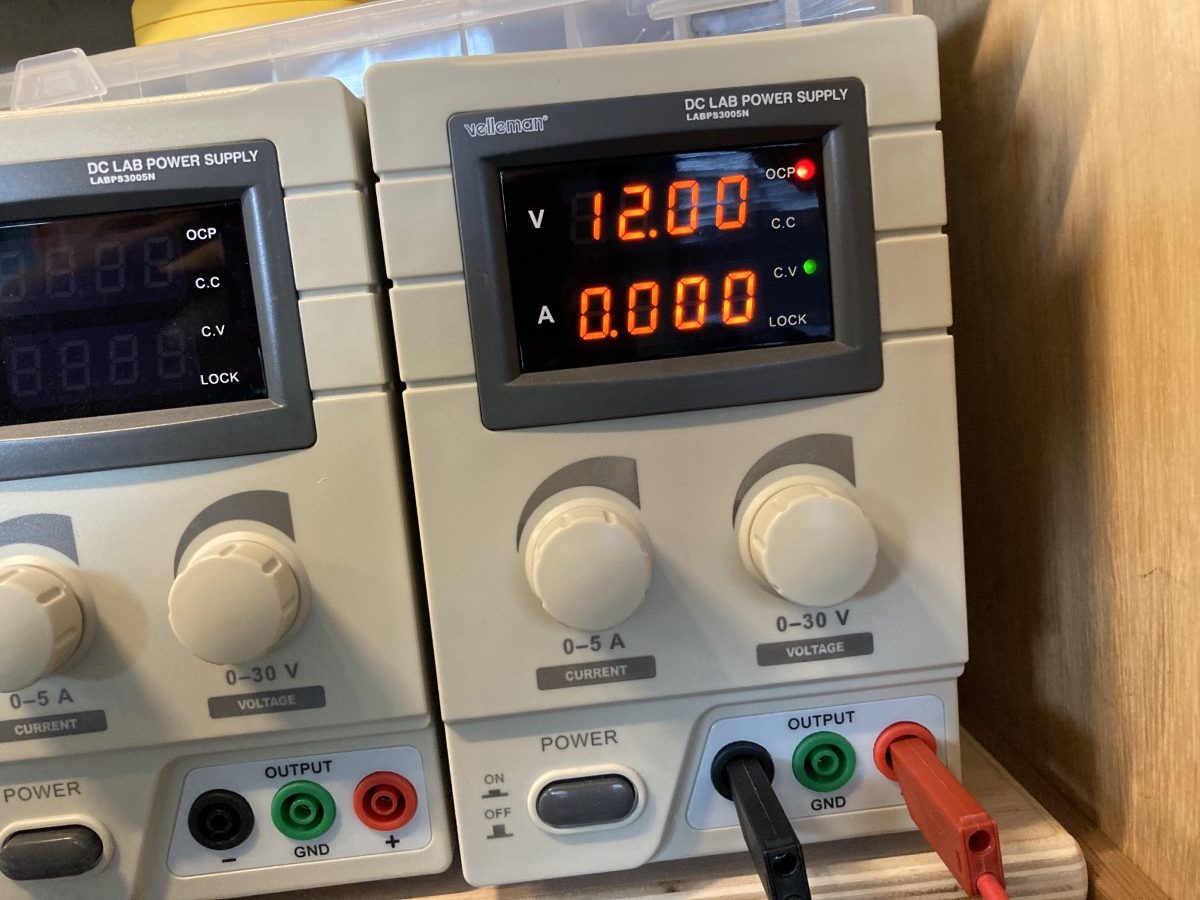
It is rather simple, using only one transistor, a couple of resistors and capacitors, and a VCC voltage of 12 Volt.
Building it
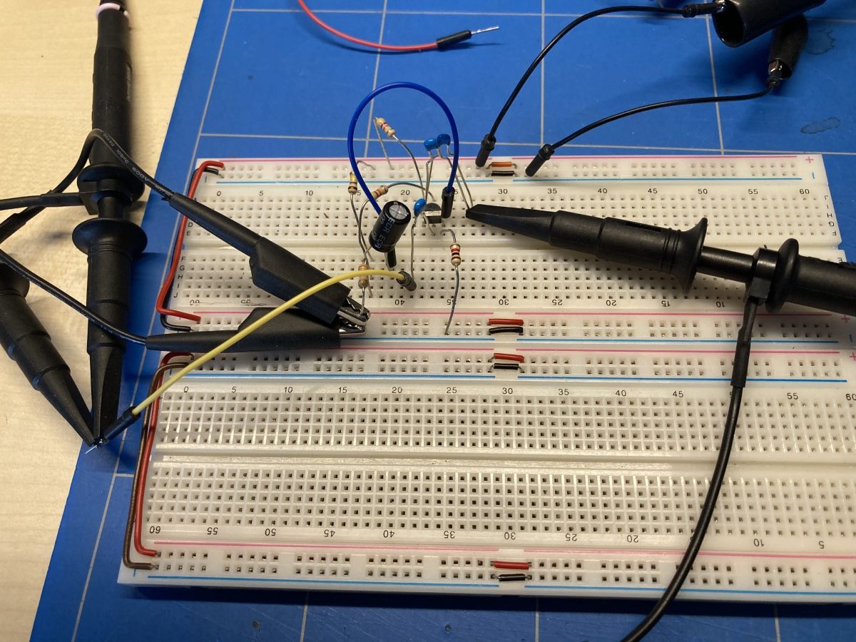
So I built this thing up on a breadboard and started to measure. See the first results in the gallery below.

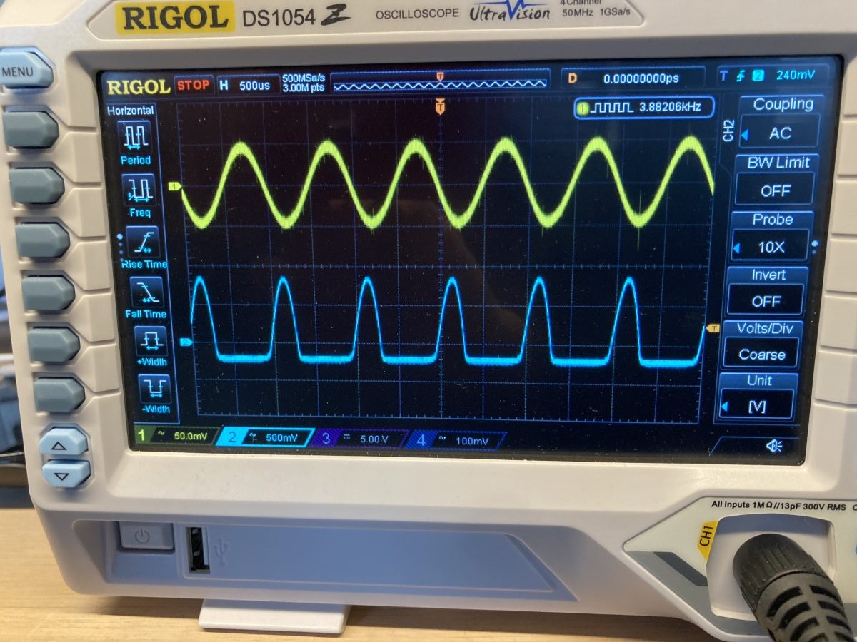
First results
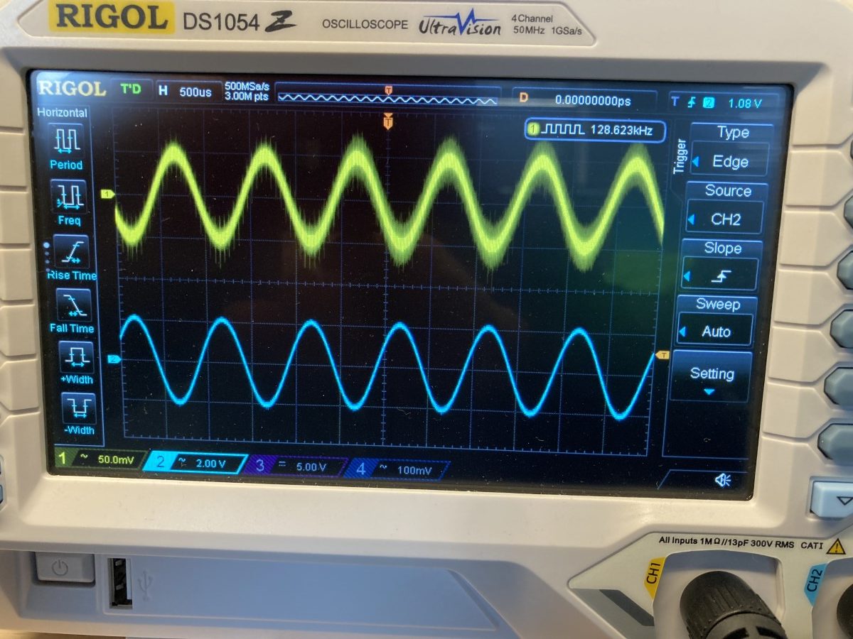
So, as you can see, not a big success. The output wave form is all wrong, the bottom half is nearly gone due to some clipping effect.
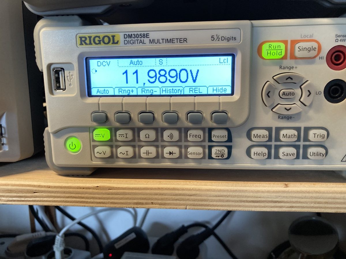
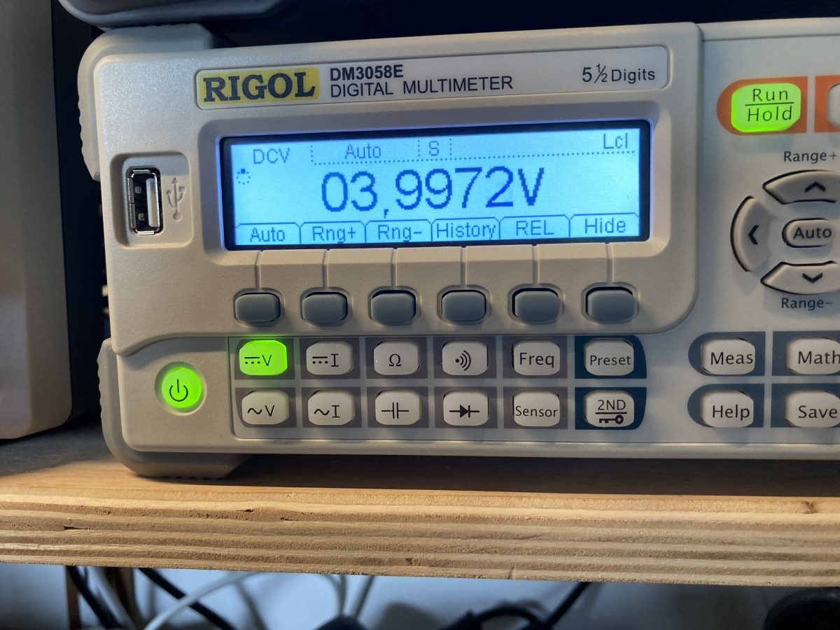
I searched some more and found that the transistor has to be set to a base voltage of about 0,65 Volt (duh, I knew that). Measuring, I found that this schematic gave me a base Voltage of 0,85 V. As you can see in the pictures below, I had to bring the VCC down to 4 Volts before I got a proper output wave form.
Correction for 12 Volt
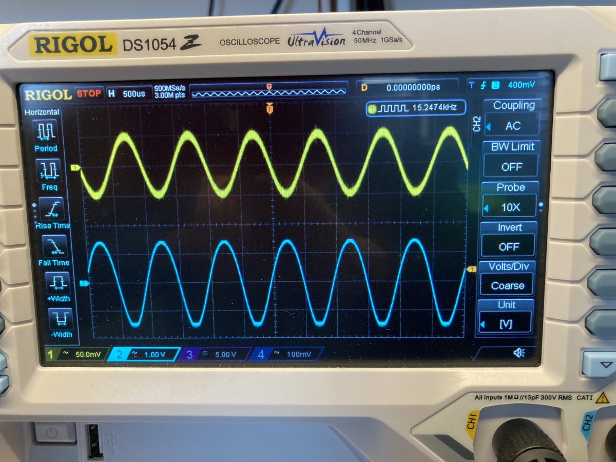
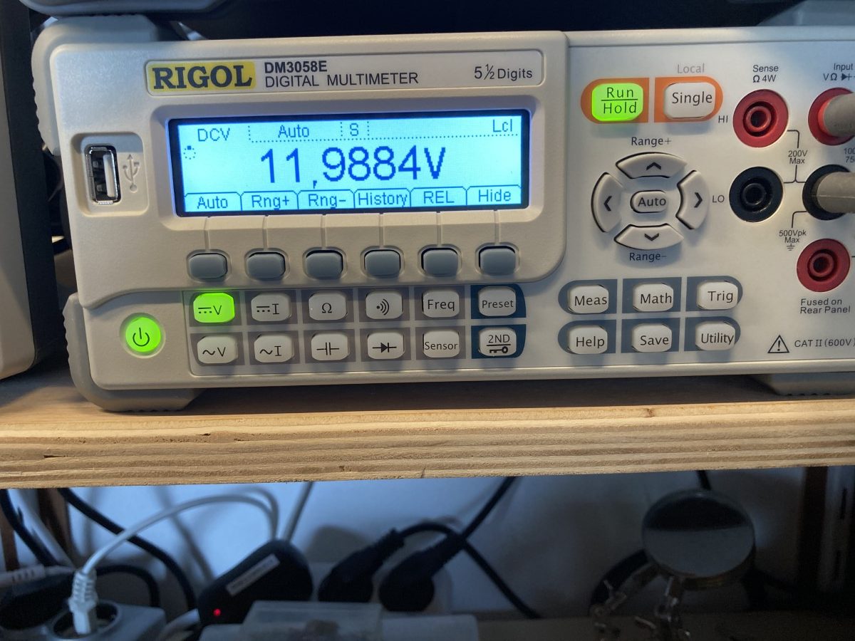
Now I started calculating what it would take to get it right for 12 Volt. The voltage divider, formed by R1 and R2, forms a ratio of 0,18. That gave us the wrong base voltage of 0,85 Volt. After a little experimenting I found that with a value of 12k for R2 the circuit worked as expected, with a 0,7V base voltage. See below:
Success!
All in all, a fun experiment, resulting in an amplification factor of about 25 at 1000 Hz.
[correction] I made this blog, not noticing that I accidentally used a 47k resistor for R4…
One Reply to “Experimenting transistor amplifiers (1)”
Comments are closed.