Totem Mini Lab – first review

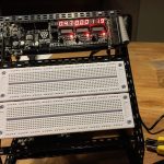
The Totem Mini Lab at work
A couple of weeks ago I came across the site of Totem. They make interesting stuff! Amongst other things they produce what they call a “Totem mini Lab” (see picture on the right, click for larger image).
This seems a good setup for lesson environments, have a look at their description on their website.
I ordered one, and reviewed it; read on for my first review!
Unboxing
My Totemmaker stuff arrived from Lithuania. All boxes are the same size, which is clever for shipping. Packaging was reasonably good, two layers of bubble wrap and one layer of thick plastic.
-
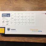
- Totem Starter Kit
-
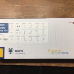
- Totem Supply Parts Kit
-
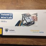
- Totem Mini Lab
-
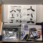
- Contents of the Mini Lab
-

- Contents of the Starter Kit
Assembly
I started with the assembly of the Totem Mini Lab. Mechanically it’s a clever design and rather sturdy after the build. Some nuts had false threads, that caused me some bolts, but there were more than were needed for the build, so no problems there. After switching it on for the first time, it immediately began running the infamous “BLINK” program.
-

- The working Totemduino
-
- Mini Lab completely assembled and working 2
-
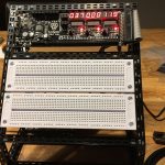
- Mini Lab completely assembled and working
-
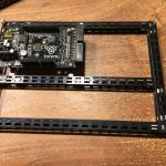
- Totemduino mounted on the base
-
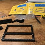
- The base of the Mini Lab assembled
-
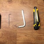
- Tools from the Starter Kit
Documentation
The documentation is technical. It shows which parts are there, it makes clear how beams can be connected in various configurations. Okay, mechanically we do not need much more, so that’s okay…
Electronically the documentation for the Mini Lab is weak. It points out which buttons there are and there are one or two sentences in pictures to give a rudimentary explanation of what they could do. But when this kit is meant for students who are just entering in the field of electronics, it is not enough; they will be lost.
Current measurement
I compared the current measurement from the Mini Lab with my bench multimeter. I Followed the manual in connecting things, see pictures below.
Idle showing 8 milli Amps
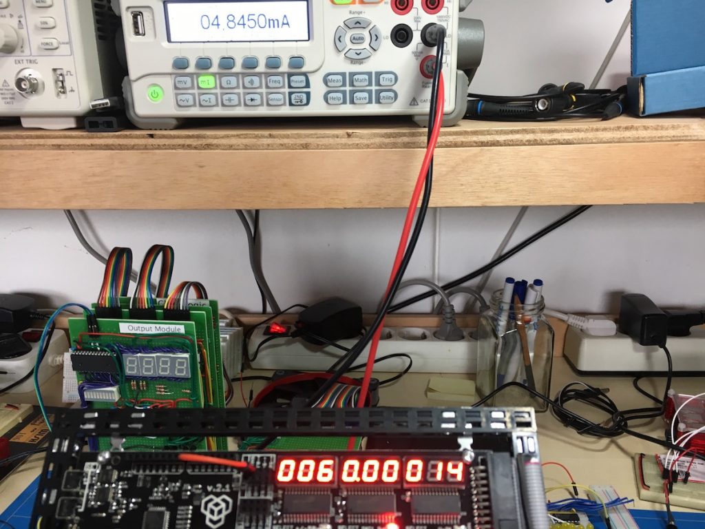
In idle mode, nothing connected, it still shows 008 mA’s (see third picture)…
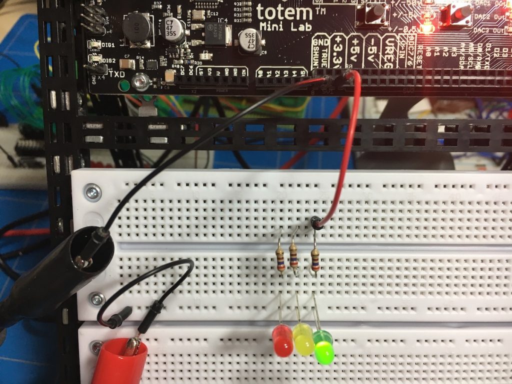
Circuit connected
Okay, so I connected a circuit consisting of one resistor (270 Ohms) and one green LED. My bench multimeter is connected in current measurement mode between GND SHUNT and the circuit GND. The bench meter gives us a reading of 4,845 mill Amps, while the Mini Lab indicates 014 milli Amps (in later measurements it was alternating between 012 and 013.
The only explanation I can think of is that the current value from the circuit has been added to the idle value.
I verified this by connecting all three LEDs with their 270 Ohm resistors in parallel. That gave me a reading of 021 mill Amps on the Mini lab and 14,38 on the bench meter. Still reasonably within the assumption that the idle current measurement is added to the actual current.
Current measurement pictures
-
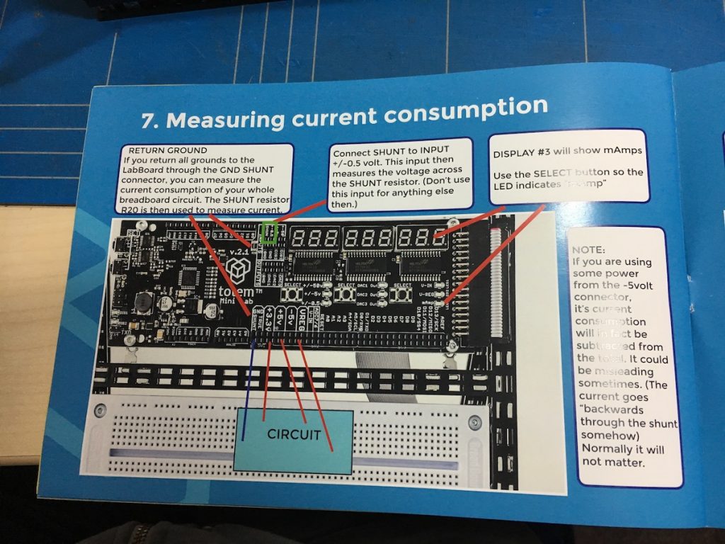
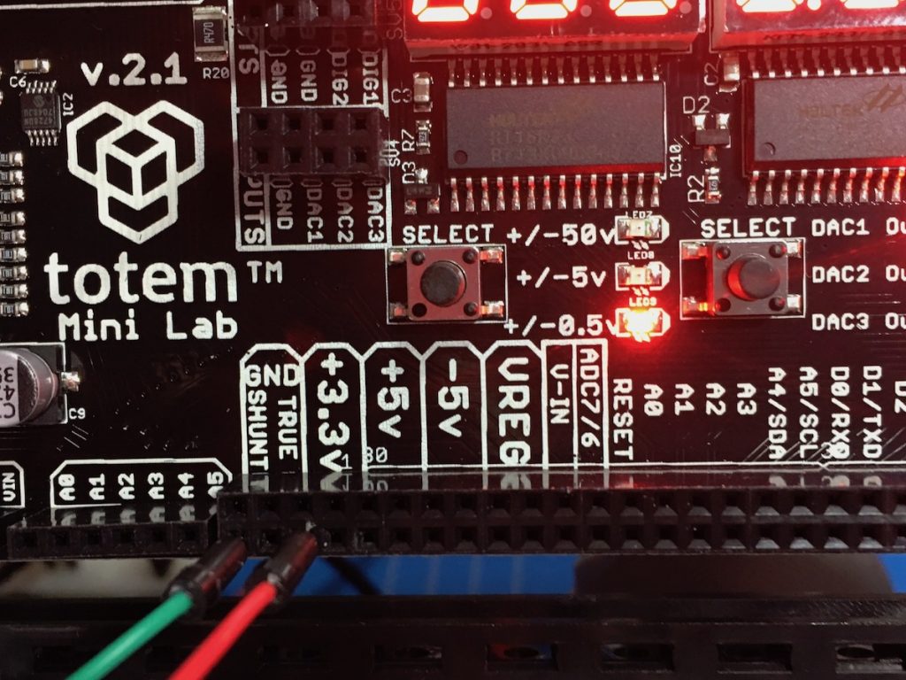
- Manual information for current measurement
-
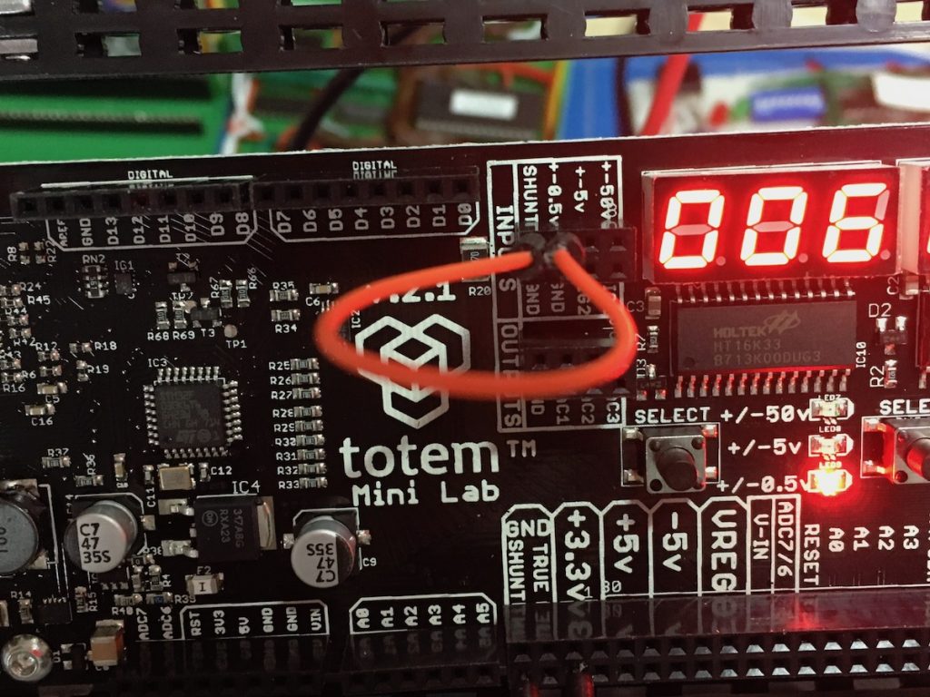
- Setup for current measurement (“SHUNT” connected to “+-0.5V”)
-
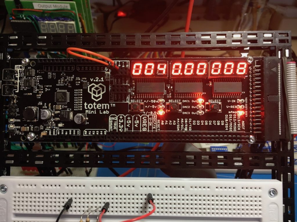
- Just setup for current measurement, nothing connected, still showing “008” milli Amperes.
-
- Circuit connected to GRND SHUNT and 3.3V
-
- My bench meter between GND SHUNT and the circuit
-
- Difference in measurements
-
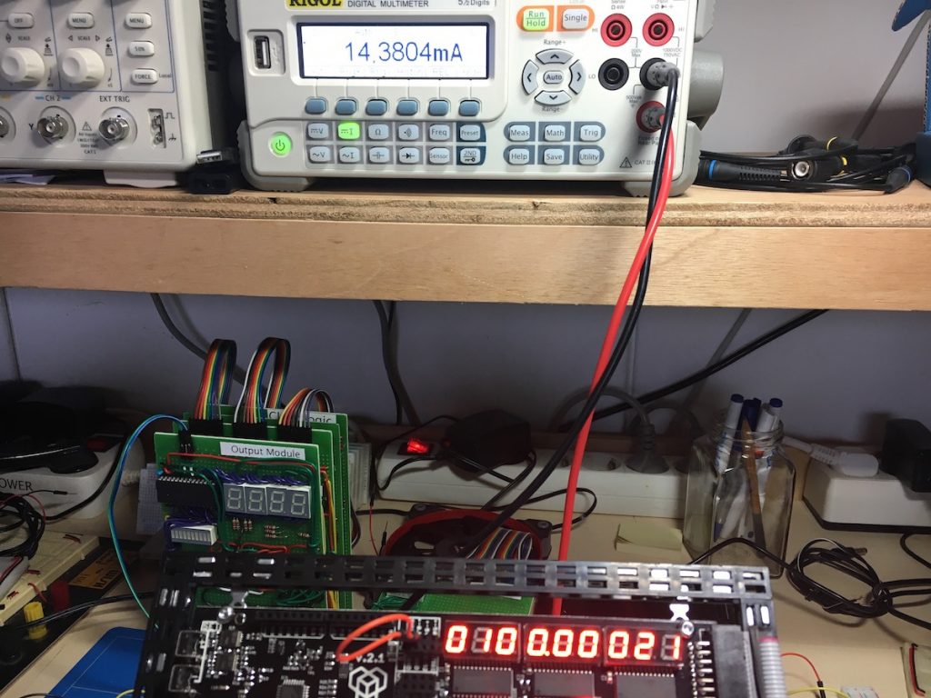
- Connected three LED’s
-

- Three connected LED’s
Voltage measurement
I proceeded by comparing voltage measurements from the Mini Lab with my bench multimeter. Here are the results of voltage measurements.
Idle showing 60 milli Volts
In idle mode, nothing connected, it still shows 0.06 Volts (even when I connect the ‘+-5V’ to GND).
Circuit connected
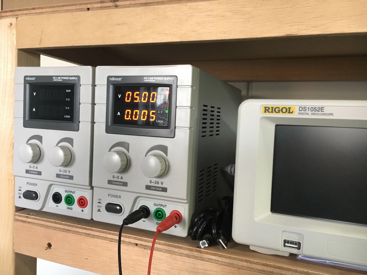
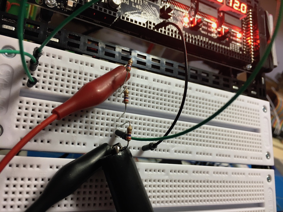
Okay, so now I connected an external power source of 5 Volts to the breadboard and connected (only) it’s GND to that of the Mini Lab. Then I connected a circuit consisting of three resistors of 270 Ohms in series between GND an the external 5Volt.
0-5 Volts range
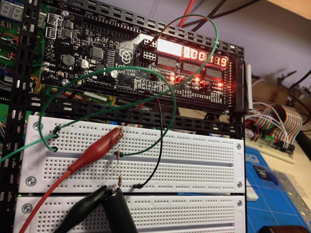
My bench multimeter – and the measurement lead for the Mini Lab – I connected at ⅓ from GND in voltage measurement mode. The bench meter gives us a reading of 1,6644 Volts, while the Mini Lab indicates 1.71 Volts (in later measurements it was alternating between 1,71 and 1,72).
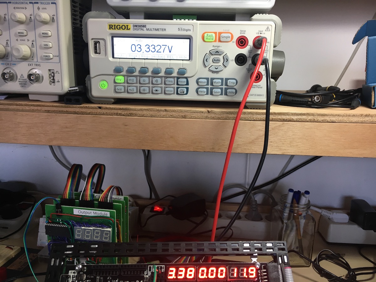
After this, I connected the measurements at ⅔ from GND in voltage measurement mode. The bench meter now gives us a reading of 3.3327 Volts, while the Mini Lab indicates 3.38 Volts (in later measurements it was alternating between 3,37 and 3,38).
0-50 Volts range
Later I changed the external power to 30 Volts and measured in the ‘+-50V’ range. At ⅓ I measured 10.0038 Volts on the bench meter and 10,4 / 10,5 Volts at the Mini Lab. This is a difference factor of 0,96, so 4% of. At ⅔ I measured 19.9856 Volts on the bench meter and 20,5 Volts at the Mini Lab, which amounts to a difference factor of 0,97, or 3 % of.
0-0,5 Volts range
After this I changed the external power to 0,5 Volts and measured in the ‘+-0.5V’ range. At ⅓ I measured 167,03 milliVolts on the bench meter and 168 milliVolts at the Mini Lab. This is a difference factor of 0,99, so 1% of. At ⅔ I measured 0,3344 Volts on the bench meter and 0,332 Volts at the Mini Lab, which amounts to a difference factor of 0,99, or 1 % of.
Result
On average the voltage measurement precision in the:
- 0-0,5Volts range is ~ 1%
- 0-5Volts range is ~ 2%
- 0-50Volts range is ~ 3%.
Voltage measurement pictures
-

- External power, 5 Volt
-

- 3 resistors in series, measuring at ⅓ from GND
-
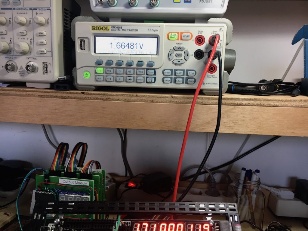
- Values at ⅓

-
- 3 resistors in series, measuring at ⅔ from GND

-

- values at ⅔
Frequency measurement
I proceeded comparing the measurements from the Mini Lab with my bench multimeter. Here are the results of frequency measurements from 1KHz to 1MHz.
I generated frequencies with my MHS 5200A function generator and set it to the frequencies specified below. As a reference measurement I used my bench multimeter, set to its frequency setting. To make things look nice, I hooked up my scope as well.
Results
| frequency | bench meter | Mini Lab | precision |
|---|---|---|---|
| 1 KHz | 999,991 Hz | 1000 Hz | +/- 1% |
| 10 KHz | 9,99994 KHz | 9986 Hz | +/- 0,5% |
| 100 KHz | 99,9995 Hz | 99858 Hz | +/- 0,2% |
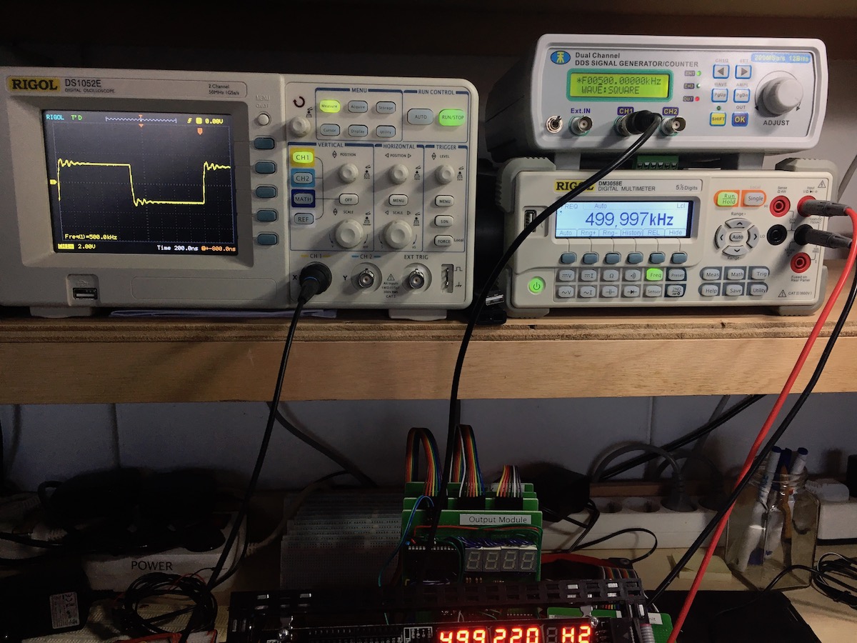
| 500 KHz | 499,997 KHz | 499220 Hz | +/- 0,2% |
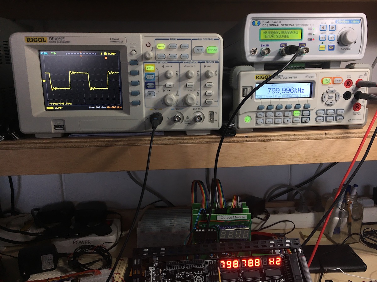
| 800 KHz | 799,996 KHz | 799788 Hz | +/- 0,1% |
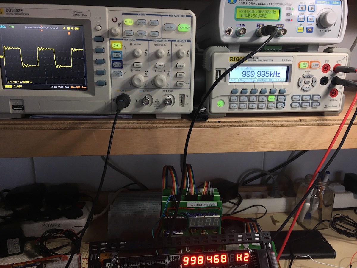
| 1 MHz | 999,995 KHz | 998468 Hz | +/- 0,05% |
Not bad at all!
Frequency measurement pictures
-
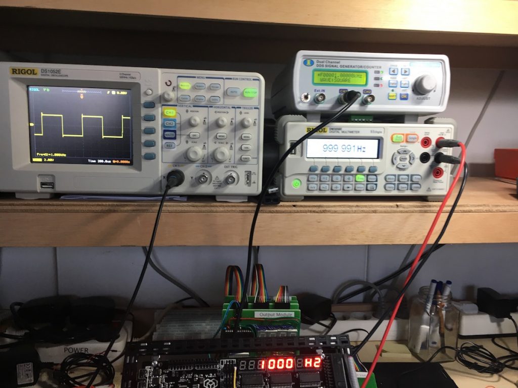
- 1 KHz

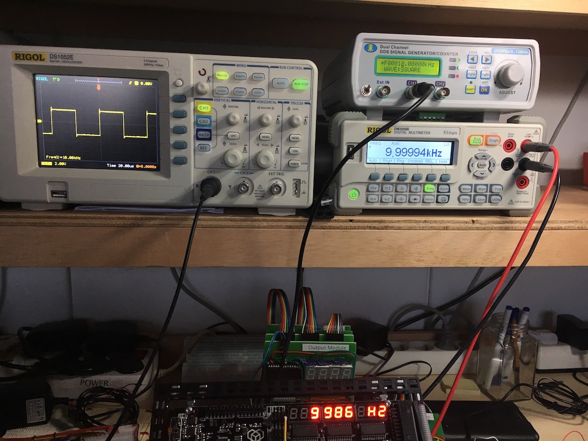
-
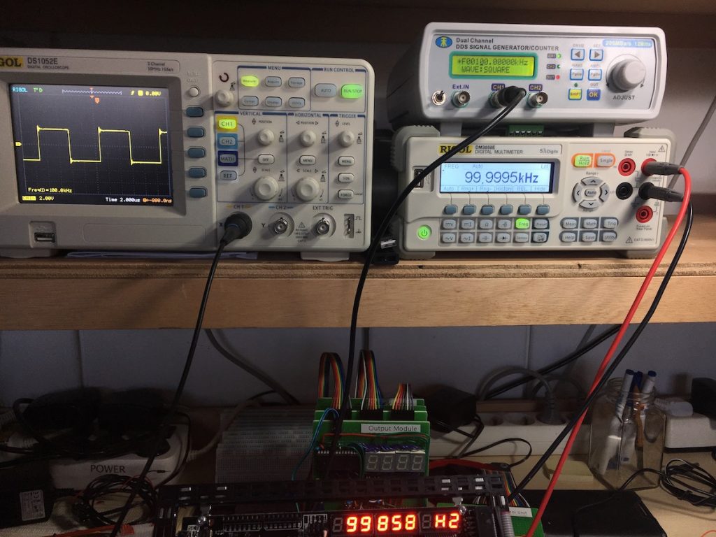
- 100 KHz

-

- 500 KHz
-

- 800 KHz
-

- 1 MHz
DAC outputs
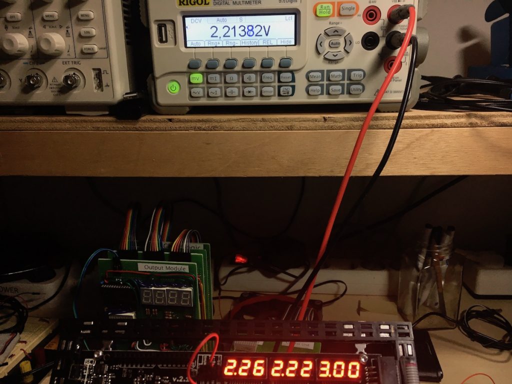
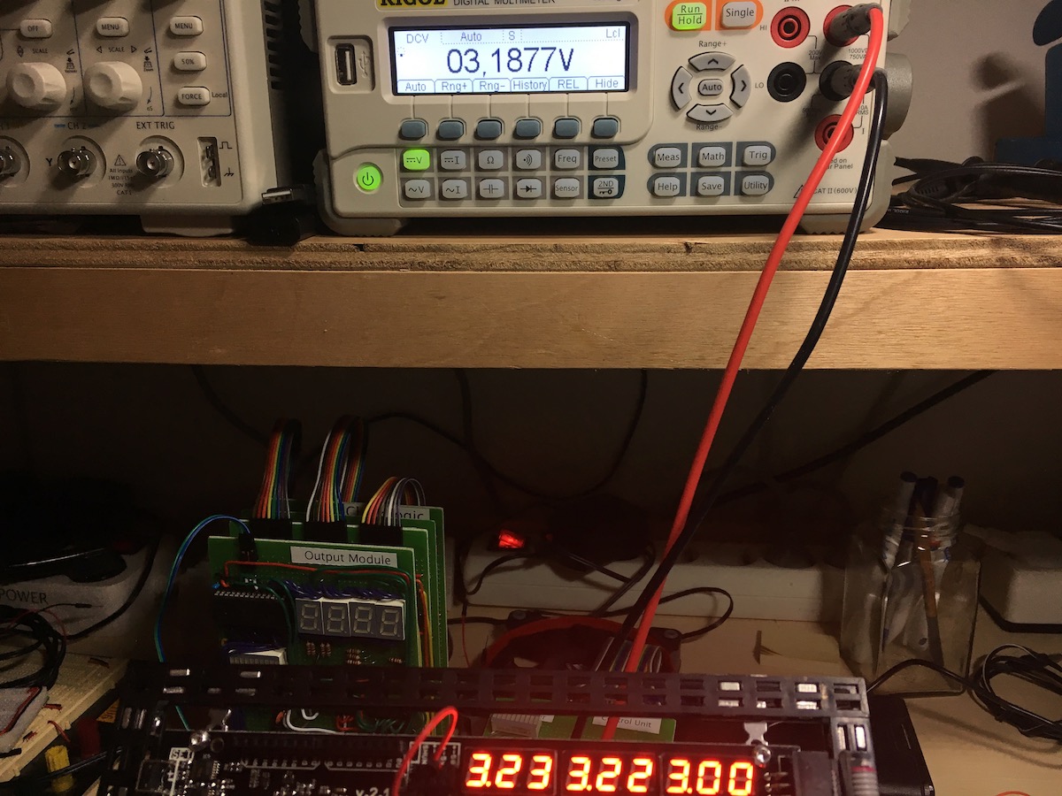
The Mini Lab has three programmable voltage outputs, DAC1-DAC3. They all can be set from 0 to 3.30 Volts. I tested them. I set DAC1 to 0,77, DAC2 to 2,22 and DAC3 to 3,22 Volts. Then I measured the actual values with my bench meter and I hooked it to the Mini Lab volt meter as well (0-5V range). The 50 milliVolt difference comes back in the miniLab measurements.
Results
| set Voltage | bench meter | precision | Mini Lab meter |
|---|---|---|---|
| 0,77 V | 0,77323 V | +/- 1% | 0,82 V |
| 2,22 V | 2,21382 | +/- 1% | 2,26 V |
| 3,22 V | 3,1877 V | +/- 1% | 3,23 V |
All in all, nice results. The Mini Lab meter is 1,5 to 2% off in this range, but we already established that.
Interface annoyance
An annoying little glitch is that when setting a DAC using the up and down buttons, when you accidentally hold the UP button just to long, it rolls over, back to zero and you have to start over again from there. I would prefer it to just stop incrementing and stick to 3.30Volts.
DAC output pictures
-
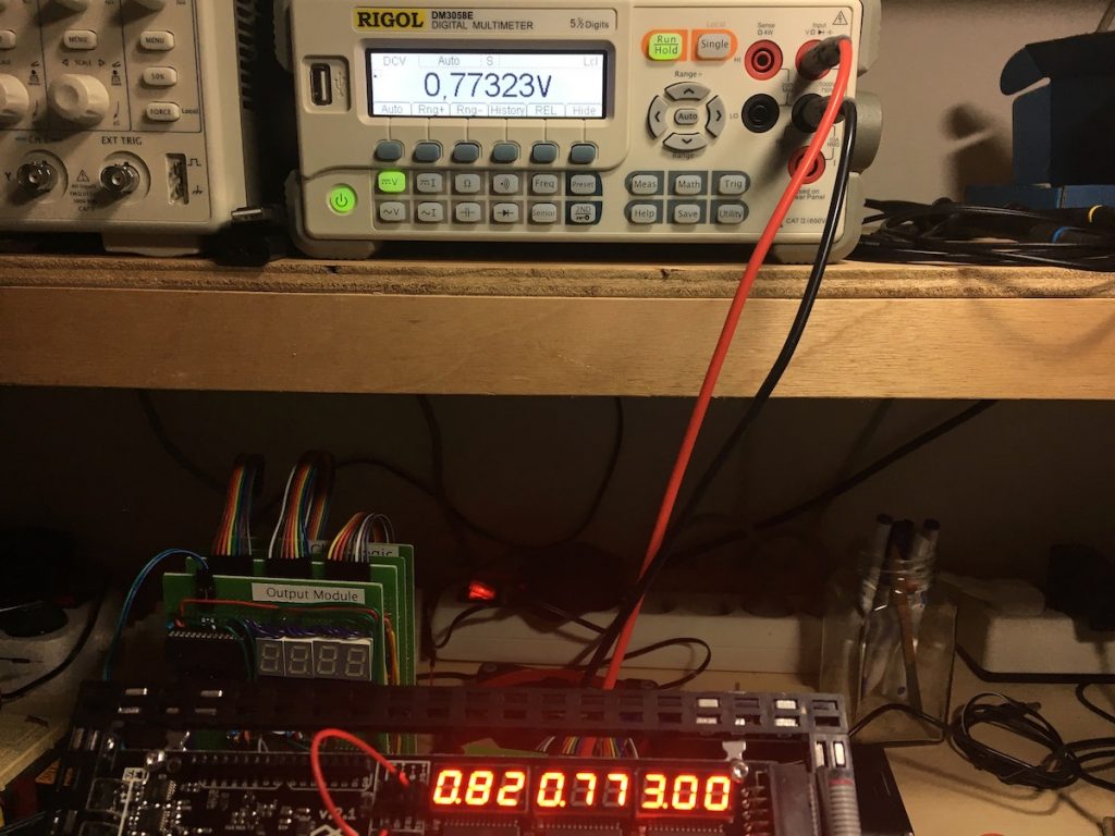
- DAC1, 0,77 Volts

-
- DAC2, 2,22 Volts

-

- DAC3, 3,22 Volts
Connecting the TotemDuino
I tried to hook up the TotemDuino to my MacBook Pro, which is basically the whole purpose of having an Arduino: being able to program and to experiment with it, right?

USB system info
No success. The USB-com port does not show up. Whatever I tried – I also had a look in the /dev directory – it did not show up.
However, in the USB section of the System Report under “About this Mac”, an entry pops up (see picture on the right).
Connect to Windows succeeded
I managed to hook up the TotemDuino up to my old Windows 7 machine and was able to program it from that machine. That’s nice, and it proves that the TotemDuino’s USB chip is not broken. It just does not seem to register a serial post on my MacBook. Which in turn is annoying, because my Windows machine is not at my electronic workbench.
Here’s the program I put in the TotemDuino:
//
// binCount
//

int num = 0; // Numer will count up (0-7)

int RED = 2; //
int YEL = 3; // Three LEDs to represent the binary number
int GRN = 4; //

int RED_stat = 0; //
int YEL_stat = 0; // Status of each LED
int GRN_stat = 0; //

unsigned long now = millis(); // Keep track
unsigned long prv = millis(); // of time

// the setup function runs once when you press reset or power the board
void setup() {
  Serial.begin(9600); // Start serial coms
  Serial.write("Hello\n"); // Greet our user
  pinMode(RED, OUTPUT); // Set all
  pinMode(YEL, OUTPUT); // three LEDs
  pinMode(GRN, OUTPUT); // to output
}

// the loop function runs over and over again forever
void loop() {
  now = millis(); // Determine time
  if ((now - prv) >= 1000) { // if a second passed
    GRN_stat = num & 1; // Calculate
    YEL_stat = (num >> 1) & 1; // three
    RED_stat = (num >> 2) & 1; // bits
    digitalWrite(RED, RED_stat); // Set
    digitalWrite(YEL, YEL_stat); // three
    digitalWrite(GRN, GRN_stat); // bits
    Serial.write("stat changed\n"); // Say something
    num = num + 1; // Increment
    if (num > 7) { // and roll over
      num = 0; // the
    } // number
    prv = now; // Save the time
  }
}
By the way: WordPress is terrible at showing code… 🙁
Conclusion
Pro’s
- The documentation about the construction materials, however comprehensive, is good, it shows the ways parts can be combined.
- A built structure is pretty sturdy, better than I expected.
- The voltage measurement is pretty good, for a reasonably simple Voltmeter.
- The frequency measurement precision was a pleasant surprise.
- The DAC’s give out voltages within 1% of their set values.
Con’s
- The documentation about the electronics part of the Mini Lab board is obviously written by engineers. The kit would really benefit from more extensive explanation – with examples – of the functions of the Mini Lab board! Especially before it can be released into the hands of beginners.
- The idle voltage and current measurements not being zero is confusing, especially for students.
- The user interface for the setting of the DAC voltages needs improvement, it rolls to zero volts when one reaches the maximum without (for obvious good reasons) the ability to roll back over zero to get back to maximum. This is very annoying.
- The TotemDuino, when connected to a MacBook Pro, does not register a COM port.
Contact with the Totem team
Of course I contacted the Totem team and gave them my feedback. They are working on the remarks I gave them. The team is responsive and friendly. Their suggestion is that I might have received a faulty board (given the idle current and the idle voltage measurement not being zero).