In the HAM course I am following to become a licensed radio amateur, the topic of resonance frequencies came along. To wrap my head around it I did some experimenting. You can find the result below. I have an assortment of capacitors and coils that I can use for these experiments.
Calculations

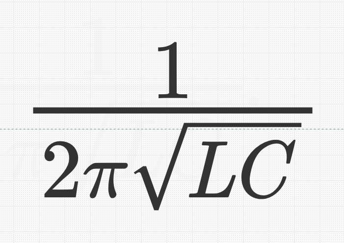
First of all, let’s have a look at the formula for the calculation of the resonance frequency of the combination of a coil (L) and a capacity (C), either in series or parallel. This formula is as follows:
So the frequency at which resonance takes place can be calculated from the values of the inductance of a coil (in Henry) and capacity (in Farad). These are very large values and for that reason they are expressed in pico-, nano-, micro-parts of these large values.
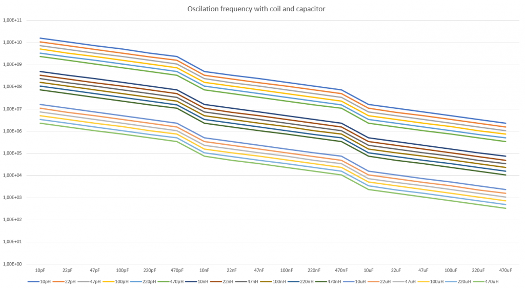
Using the formula and the values of the assortments I mentioned, I constructed a spreadsheet and a graph. The graph came out as follows:

On the vertical axis we see the see the frequency (in Herz); on the horizontal axes we can see the values of the capacitors and in the graph we see colored lines for each value of inductance from the coils, indicating at which frequency resonance should take place for the values of the L and the C..
Experiment
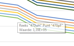
Now I chose a point on the bottom green line, see picture on the right. That point indicates that when we take a C with a value of 470pF (pico Farad) in combination with an L with a value of 470uH (micro Henry), we should see resonance at 339 kHz.
I took those components and stuck them in a breadboard, see below.

Capacitor and coil are connected in parallel, and together they are in series with a resistor to limit the current to a safe level for my signal generator. This signal generator is set up to generate a sine wave, sweeping from 250 kHz to 400 kHz in as short a time as it can do (in this case just over 14 ms. See picture below.

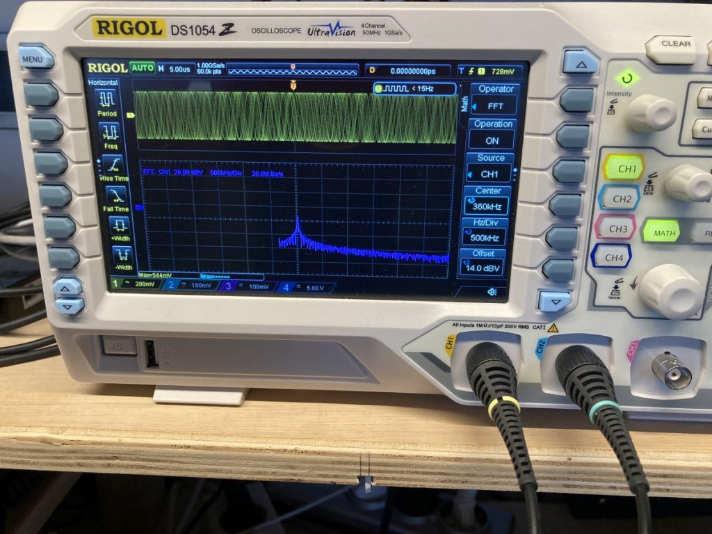
With my oscilloscope I measured the signal over the circuit in the voltage domain and also measured through the FFT mode in the frequency domain. Below you can see the voltage of the signal in yellow on the top half of the screen, with the frequency domain below that.

Because a circuit where L and C are connected in parallel has a very high impedance I expected to see a dip in signal strength around 339 kHz. Instead I saw a peak around 360 kHz.
First let’s have a look at the resonance frequency. I did some measurements. The coil appeared to have a value of 454,4 uH instead of 470 uH. The capacitor appeared to have a value of 420,4 pF instead of 470 pF. When we insert these values into the formula we get a resonance frequency of 364 kHz. So that explains the frequency difference.
Then, let’s have a look at the peak instead of the expected dip (expected by me). But then I realized that this high impedance causes the higher voltage!

One Reply to “Resonance frequencies”
Comments are closed.