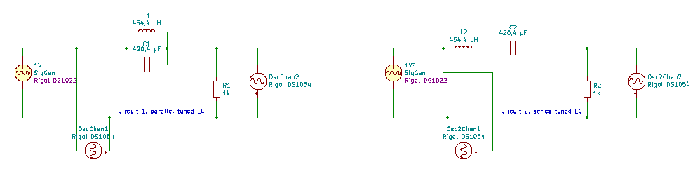
Yesterday I started with Capacitors / capacity and coils / inductance. Today I did some extensive measuring, first on a C and L in a series tuned circuit, then on a parallel tuned circuit. See schematics here below:
For these measurements I used the same setup as yesterday. But this time I did not let it sweep across a frequency range, but I manually went from 10 kHz to 730 kHz in 10 kHz increments. At each stop I put the output voltage of the filters in a sheet.
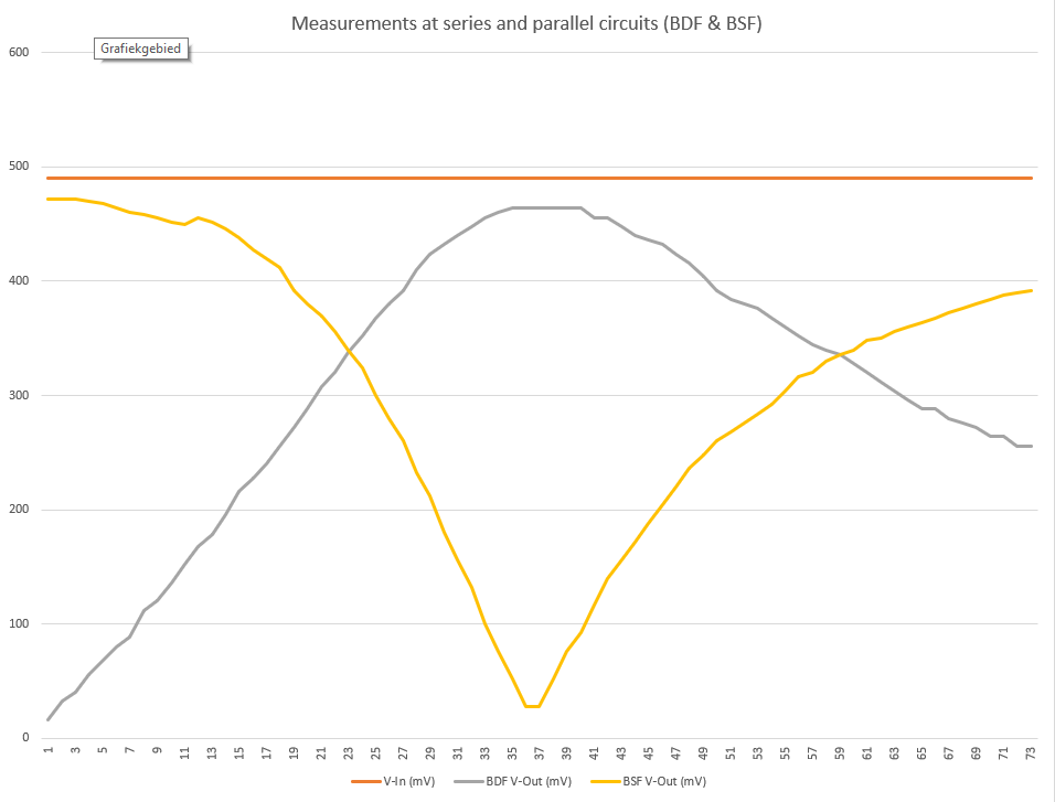
This gave some insight in the principle characteristics of band filtering. As you can see in my previous post, the resonance frequency was near 364 kHz. This can also be seen perfectly in the resulting graph.
In the graph below you can see:
- input voltage from the signal generator (horizontal orange line).
- output from the parallel tuned circuit Band Pass Filter (yellow line)
- output from the series tuned circuit Band Stop Filter (grey line)