Today I take it up a notch, by making a two transistor amplifier. This time I use the circuit diagram at the right (published on Jos Verstraten’s website).
As a convenient touch, measuring points are given in the diagram, indicating the expected Voltages.
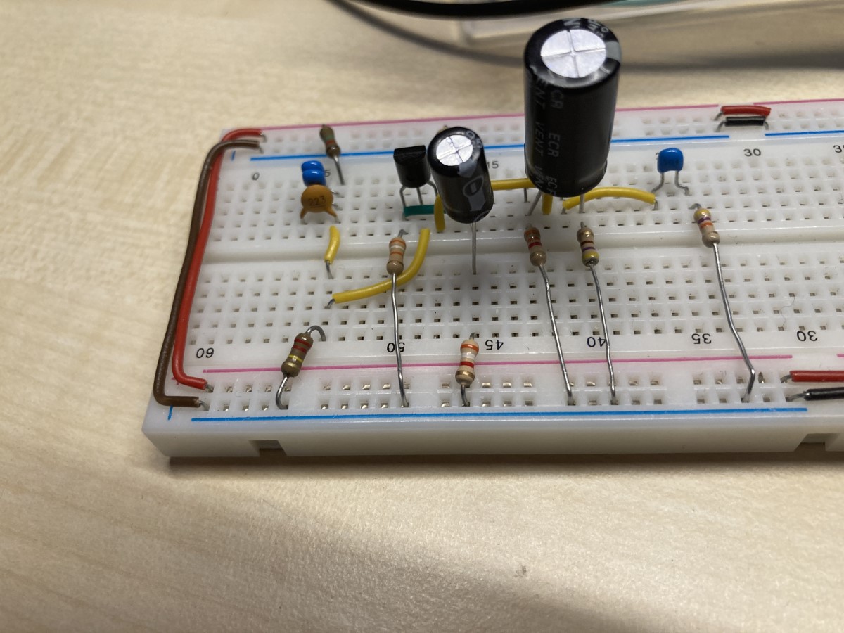
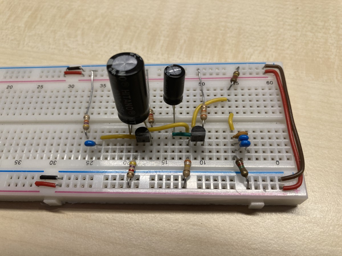
Building the circuit
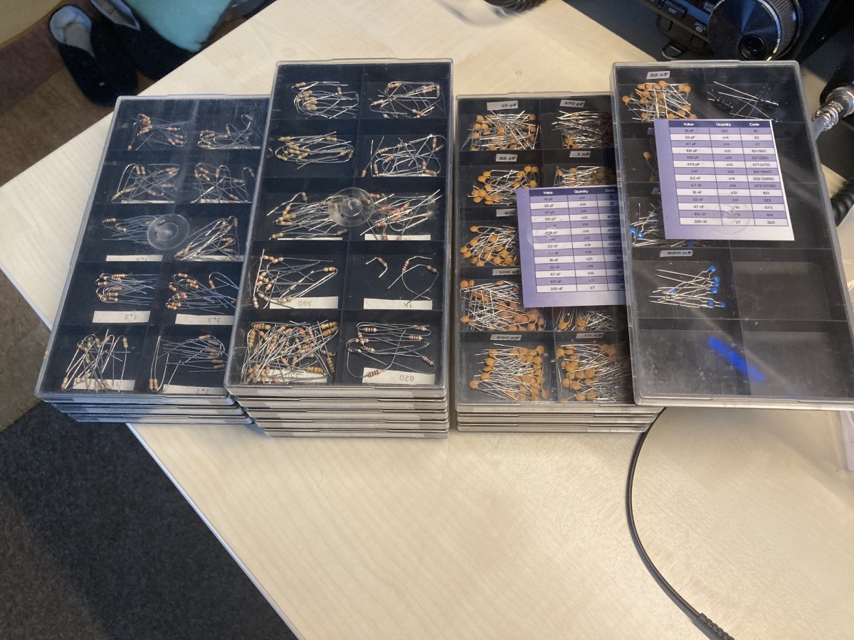
We begin by getting the components and building up the circuit:
Hook it up
Now we hook it up to power, 20 Volts this time:


Measuring
First voltage measurements of the points from the diagram indicated that we are a bit of spec, but not to far IMHO. Probably caused by the use of BC337 transistors instead of the given B549C…
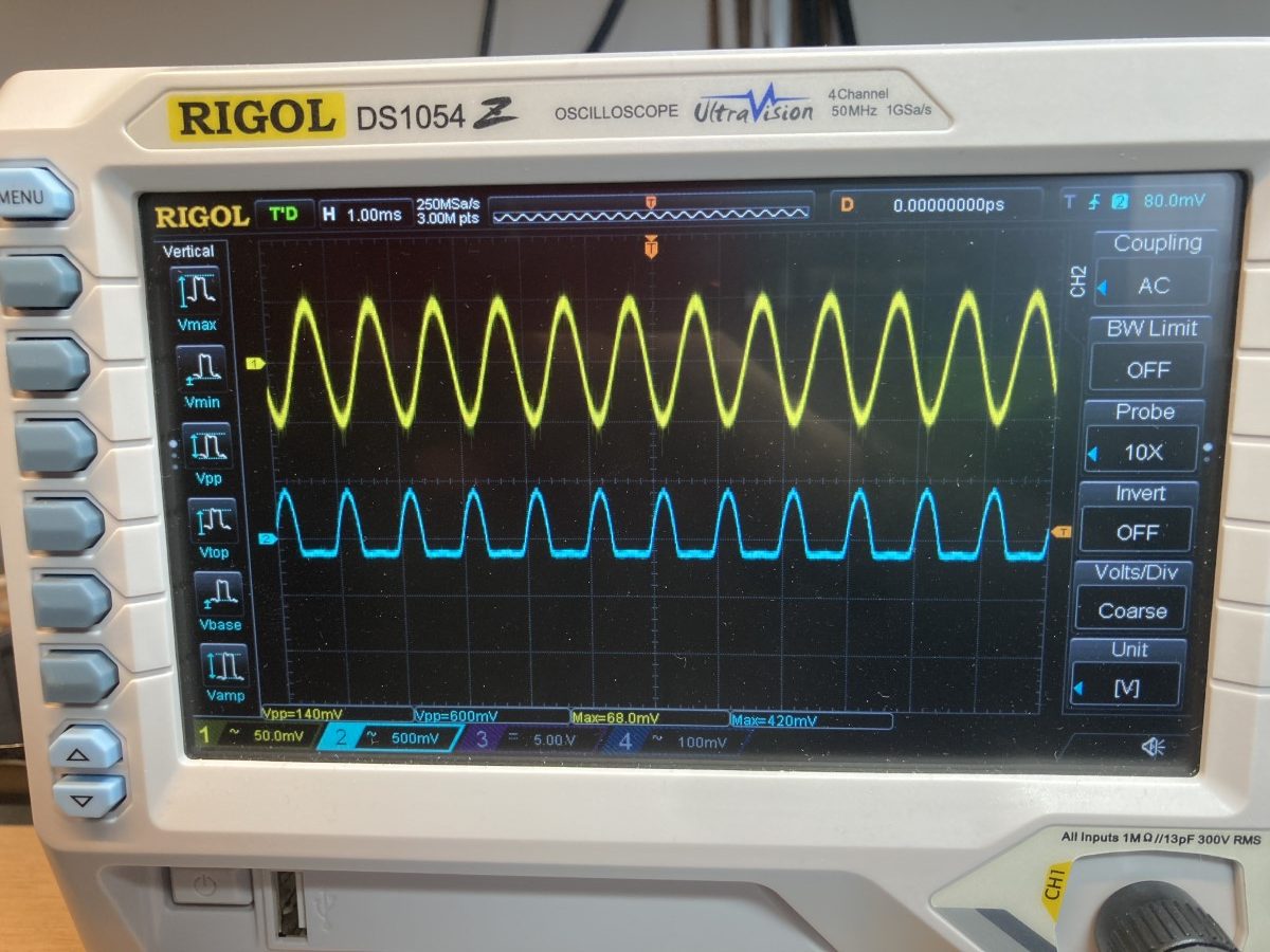
Clipping
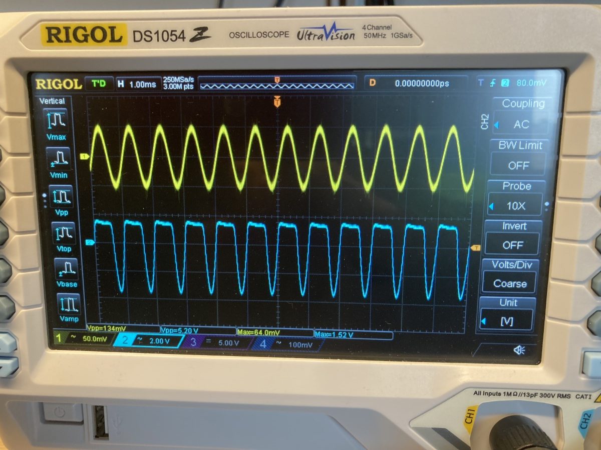
Looking at input and output we see a different story, it’s clipping, at the top this time.
The amplification seems to be a lot better; from 64mV to 1.52V, is an amplification of almost 24 times.
By the way, here in the output you can see that the signal is in phase with the input.
Poking around
Now I measured between the collector of T1 and the base of T2. That is the output of stage 1.
As you can see, the clipping already takes place in the first stage of the amplifier.
Here you see the output of the first stage is out of phase (inverted).
Fiddling to get it right
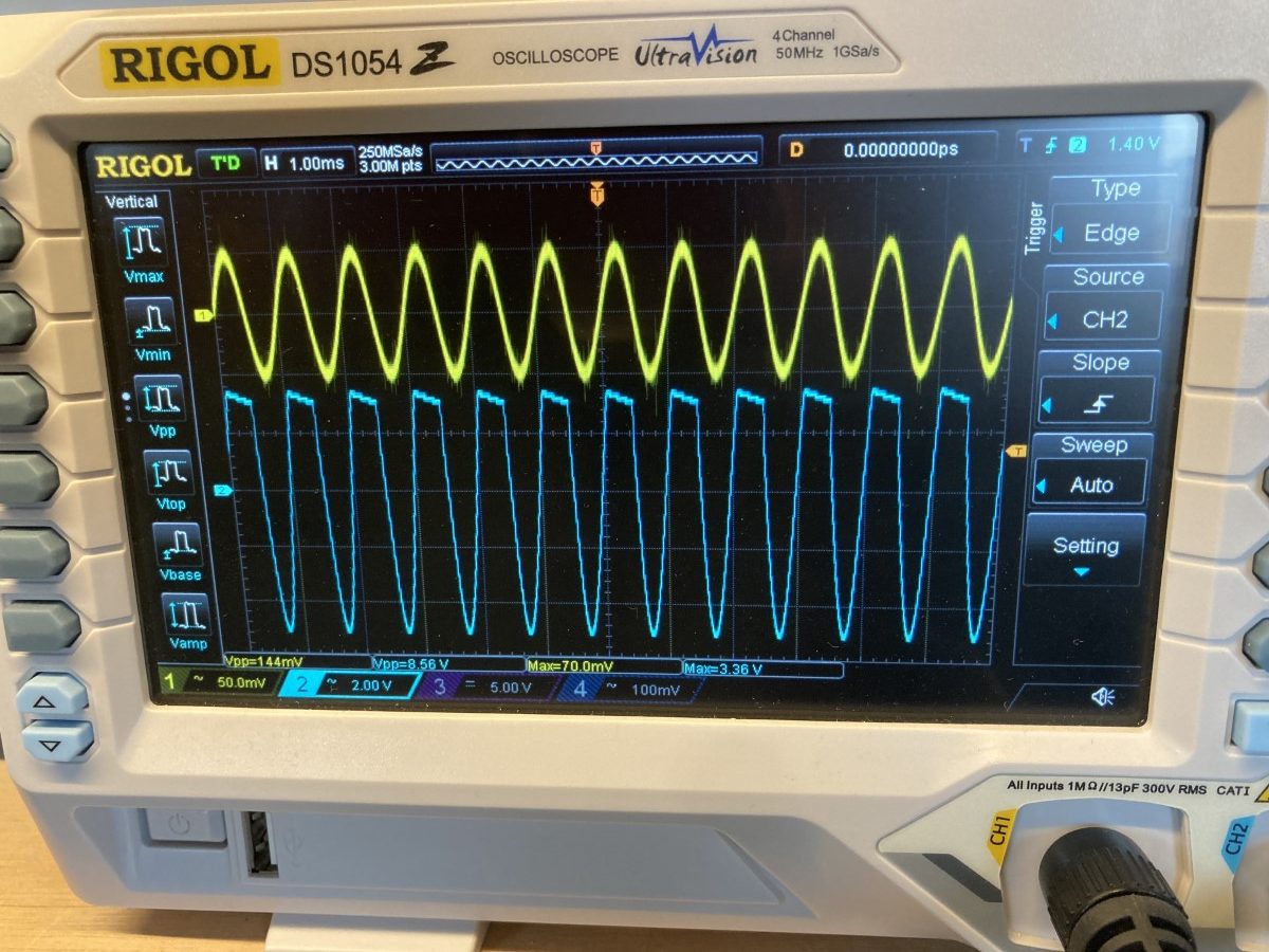
At this point I was substituting some resistors to get rid of the clipping. After some experimenting I still couldn’t get it exactly right. It is still clipping, the amplification has gone up, 3,36V divided by 70mV yields a factor of about 48 time…
Brain wave
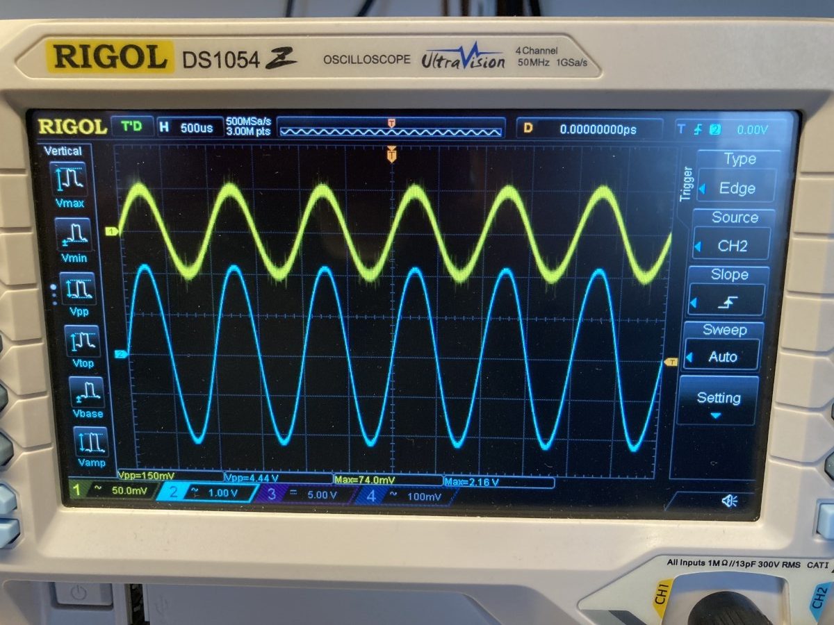
After a while, I realized that perhaps fiddling with the bias of T1 wasn’t enough.
I decided to instead alter the amplification of the first stage by replacing R5 with a 15k resistor. That worked as you can see in the last picture.
The amplification even went down again, to around 30, but there’s no more clipping!
Success
All in all a fun experiment…